Minimizing Circuit Uncertainty
Making circuit failures visible.
Have you ever built a circuit that should work - only to spend hours debugging before realizing one component was defective? That uncertainty was the problem my team and I were tasked with addressing for the Duke BME electronics labs.
Students were spending valuable lab time troubleshooting systems that were electrically sound, except for one hidden variable: a faulty chip. There was no quick way to verify if the chip was working - so we set out to design one.
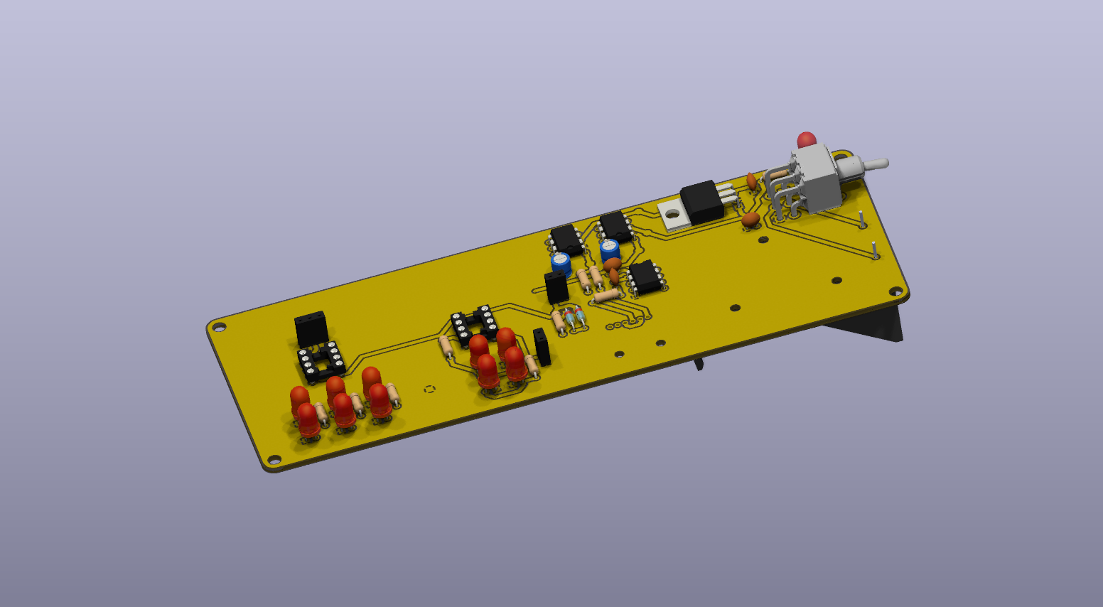
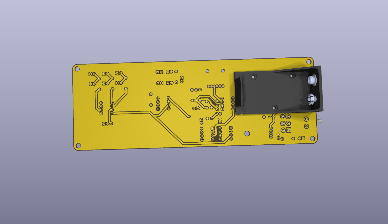
Our solution was a dedicated PCB chip tester that allows the chip to be connected in isolation. By removing the chip from the larger circuit and placing it into a controlled testing environment, users can immediately observe LED outputs that validate core functionality.
Technical Highlights:
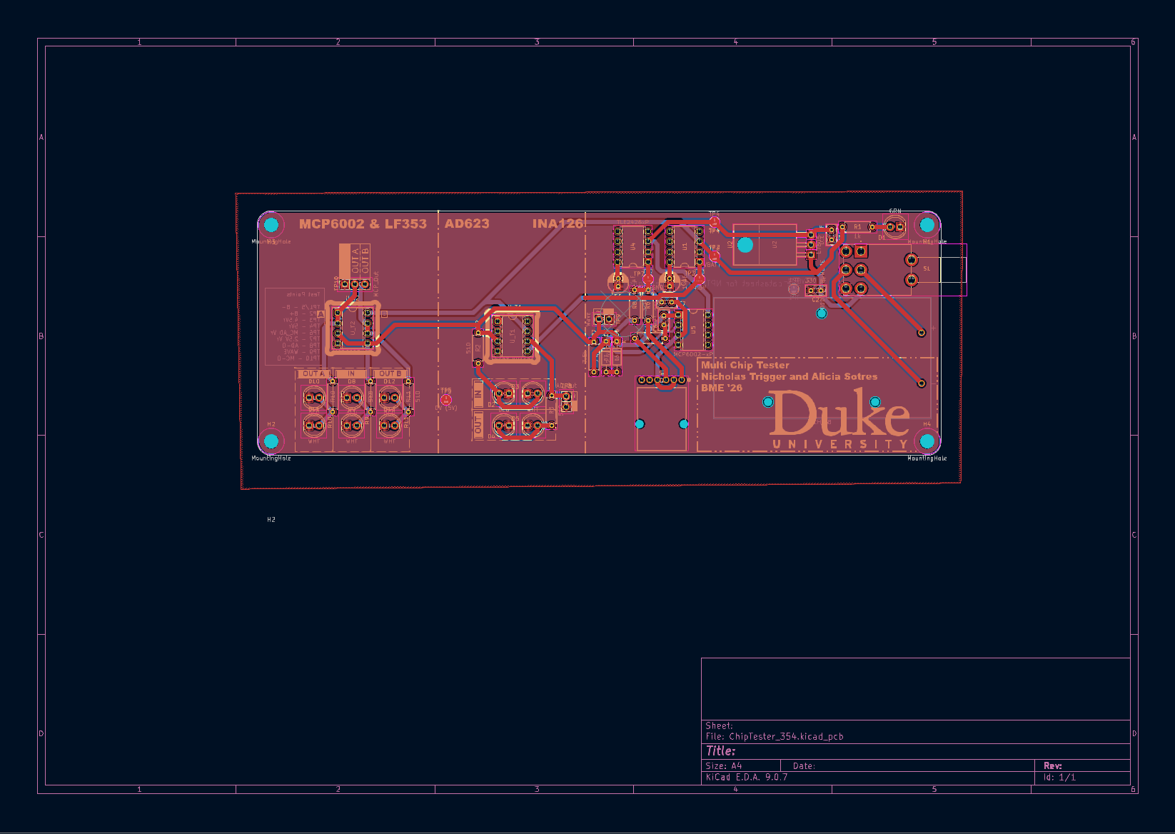
Designed a multi-chip validation PCB capable of testing instrumentation amplifiers (AD623, INA126) and operational amplifiers (MCP6002, LF353)
Designed in Kicad.
Designed and integrated a Schmitt trigger oscillator circuit to generate stable test waveforms for LED blinking and functional verification
Powered by a 9V battery, enabling a fully portable testing platform.
Implemented LED-based output indicators to provide immediate visual confirmation of chip behavior